Back to the product list

Exhaust Assembly

Waveguides are normally pressurized with dry air to protect them from the negative effects of moisture, such as corrosion and signal degradation. Even when waveguide windows have very low water vapor transmission rates, moisture from the surrounding ambient air can still diffuse slowly into the system over time. The Delair Exhaust Assembly is designed to address this phenomenon by ensuring continuous removal of introduced water vapor, maintaining stable humidity conditions inside the waveguide. Used in combination with Delair waveguide dryers, the exhaust assembly provides an effective and controlled method of moisture management in critical microwave and RF transmission systems.

If the wave guide is very tight, there is too little suppletion of dry air to the wave guide. Therefore Delair has developed two systems to prevent the disadvantages of this phenomenon. One of these is a bleeding system by means of an exhaust assembly.

Moisture Diffusion in Waveguides

Although waveguides are engineered to be tight, they are not completely impermeable to water vapor. Over time, moisture from the surrounding environment can diffuse through window materials and seals. If the waveguide is too tight, the natural replenishment of dry air may be insufficient to compensate for this diffusion. This can lead to gradual moisture accumulation, increasing the risk of corrosion and signal loss.

The Delair exhaust assembly is designed specifically to counteract this effect by enabling controlled bleeding of air from the system

Exhaust Bleeding Principle

The exhaust assembly operates on a continuous bleeding principle. A very small amount of air is continuously exhausted from the waveguide to the atmosphere. This process removes any water vapor that has entered the system through diffusion. The exhausted air is then replaced by dry air supplied by the connected dryer, maintaining a stable internal environment.

This controlled exhaust approach ensures effective moisture removal without causing pressure instability in the waveguide system.

Capillary Orifice Design

At the core of the exhaust assembly is a precisely calibrated capillary orifice housed in a rigid stainless steel body. The orifice is not adjustable and is selected based on the operating pressure of the waveguide system. This design ensures a consistent and predictable exhaust flow rate, which is essential for reliable humidity control.

The exhaust assembly is typically fitted at the end of a waveguide, or at a connection between two waveguides, depending on system configuration.

System Selection and Application

Several exhaust assembly types are available to match different waveguide volumes, operating pressures, and dryer capacities. The smallest type is designed for very low exhaust flows, making it suitable for compact waveguide systems. Proper selection ensures effective moisture removal while maintaining system pressure within acceptable limits.

The exhaust assembly is commonly used in telecommunications, broadcast, and other applications where stable signal transmission and long‑term equipment protection are critical.

MOIST AIR
Wave guides are normally pressurized with dry air to prevent the disadvantages of moist air and condensate resulting in corrosion and loss of signal. Although the water vapour transmission of the windows of the wave guide is very low, a continuous diffusion of water molecules from the moist ambient air will diffuse through the window material.


EXHAUST ASSEMBLY
If the wave guide is very tight, there is too little suppletion of dry air to the wave guide. Therefore Delair has developed two systems to prevent the disadvantages of this phenomenon. One of these is a bleeding system
by means of an exhaust assembly. In case of application of an exhaust assembly a very small amount of air is continuously exhausted from the antenna to the atmosphere, so removing possibly introduced water vapour. Dry air is supplied by the dryer again.
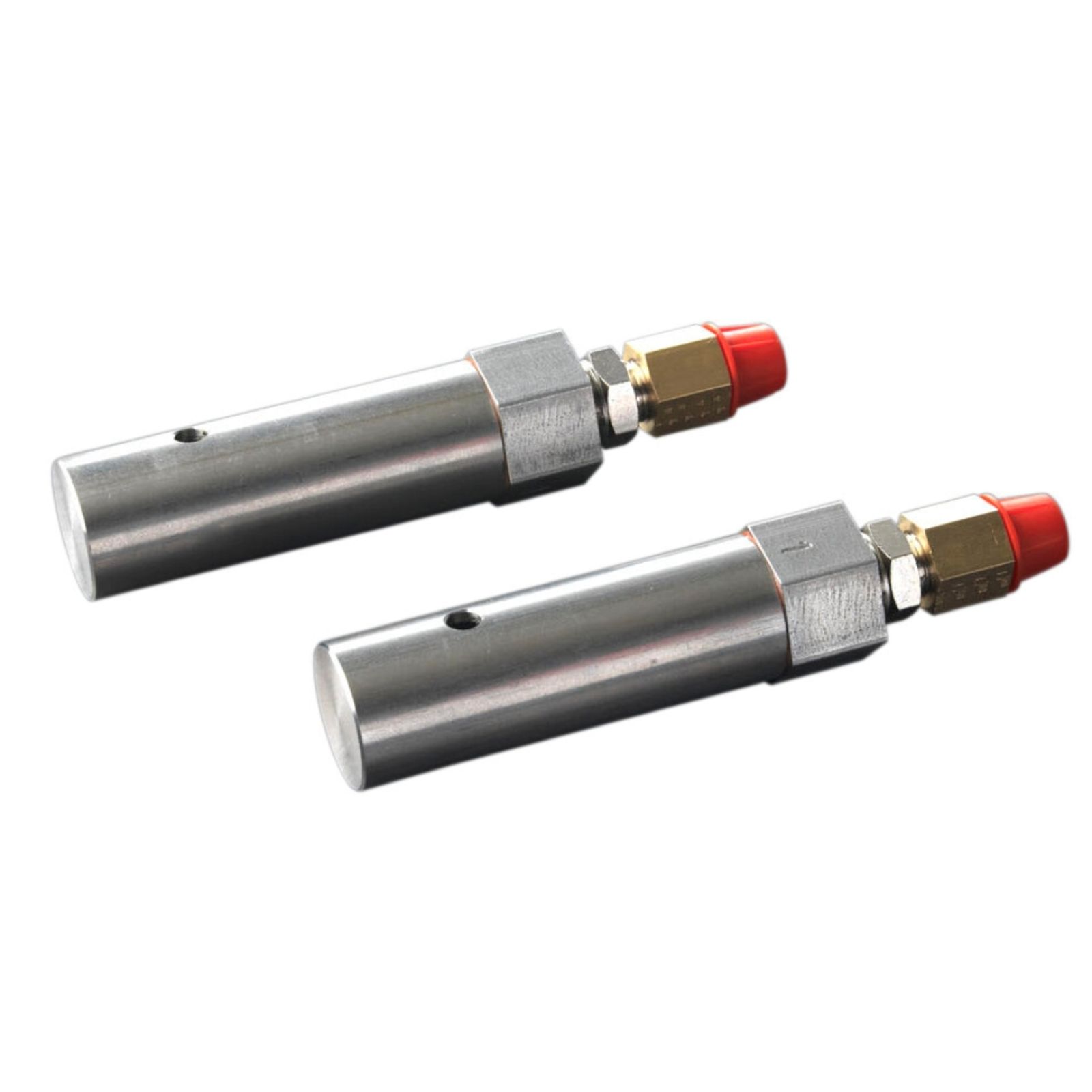

CAPILLARY TUBE
The exhaust assembly consists of a rigid stainless steel housing, in which a very precisely calibrated orifice is mounted. It should be fitted to the end of the wave guide, a combination of two wave guides or otherwise. This special orifice is not adjustable. The amount depends on the wave guide pressure.


TYPES
There are several types available. The smallest one is suited to exhaust 0.5 l/h at 10-15 mbar, intended for the smallest wave guides. The selection of the type depends on the volume and the operating pressure of the wave guide and the capacity of the dryer.

Model

Average Capacity (l/h)

Dimension

Connection

10–15 mbar

20–30 mbar

40–80 mbar

EXH1

0.5

1.5

3.5

22X80

1/4"BSP fem.

EXH2

1

3.5

5

22X80

1/4"BSP fem.

EXH3

1.5

5.5

6.5

22X80

1/4"BSP fem.

FAQs

Even tightly sealed waveguides are subject to moisture diffusion from the surrounding environment. Over time, this moisture can accumulate and cause corrosion or signal degradation. An exhaust assembly ensures that any introduced water vapor is continuously removed, maintaining a dry internal environment.